
Table of Contents
Press the power button and a two-pin short on a front-panel header wakes the chipset. The chipset nudges the CPU, which fetches its first instruction from a small flash chip soldered near the socket. Eighteen seconds later you’re dragging a browser window across the screen. Every step of that sequence travelled along copper traces etched into a board of fibre-glass and resin roughly 30 cm across.
That board is the part people install first and think about last. Here’s how it actually joins the pieces together.
The motherboard’s real job: routing, not computing
A motherboard performs almost no calculation of its own. It’s an interconnect fabric, a power distributor, and a mechanical mount all at once. A typical ATX board uses six to eight layers of copper sandwiched between layers of FR-4 substrate, and the traces carrying data are cut to precise widths so that signals arrive together. A PCIe 5.0 lane runs at 32 gigatransfers per second, which means the copper geometry matters as much as the silicon at either end.
Every component you add plugs into one of three things: a socket, a slot, or a header. Learning to tell them apart is most of the battle.

The CPU socket: the shortest and most important link
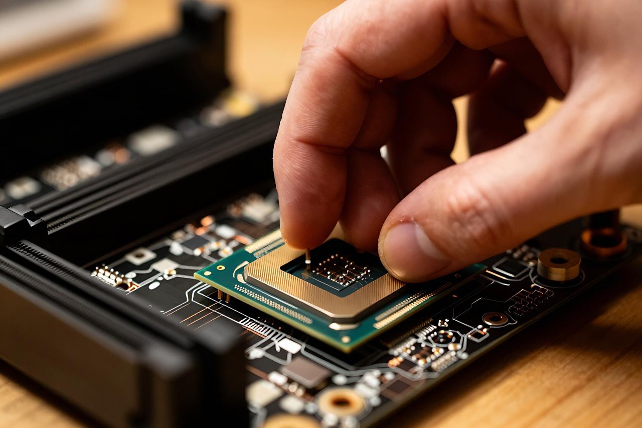
The processor sits in a socket that carries hundreds or thousands of contacts. Intel’s LGA1700 has 1,700 spring-loaded pins on the board side; AMD’s AM5 has 1,718. In both designs the pins live on the motherboard, which is why bending one is a repair job rather than an inconvenience.
What travels through the socket
Three things cross that interface continually. Power arrives from the voltage regulator modules sitting beside the socket, typically stepped down to around 1.1 to 1.3 volts. Memory traffic runs from the CPU’s integrated controller straight to the DIMM slots. And high-speed lanes go out to the primary graphics slot and the first M.2 drive, bypassing the chipset entirely.
That last detail explains a common surprise. On most boards, the top PCIe x16 slot and the first M.2 socket are wired directly to the CPU, so they stay fast regardless of what else is plugged in. The remaining slots share bandwidth managed by the chipset.
Memory slots and the dual-channel path
A DIMM slot is a 288-pin connector for DDR5 (260 pins on older DDR4), and the traces from each slot run to the CPU in matched pairs. Populate only one channel and you halve the available bandwidth — a genuine loss of several frames per second in games and a noticeable hit in video encoding.
This is why manuals tell you to use slots A2 and B2, the second and fourth from the CPU, when installing two sticks. Those slots sit at the end of the trace run, which gives the cleanest signal. Four single-rank sticks on a DDR5 board often force a lower stable speed, so 2×16 GB at 6000 MT/s usually beats 4×8 GB at the same rating.
PCIe slots: expansion without a fixed purpose
Peripheral Component Interconnect Express is a serial, point-to-point link, and a full-length x16 slot carries sixteen lanes. A graphics card in a PCIe 4.0 x16 slot can pull about 32 GB/s in each direction. A capture card or a network adapter in an x4 slot gets a quarter of that, which is plenty for its needs.
Slots are physically keyed so a small card fits a big slot but not the reverse. You can run an x1 sound card in an x16 slot without harm; you cannot run a graphics card in an x1 slot at all. Check the board manual for which slots share lanes — on many mid-range boards, filling the second M.2 socket disables two SATA ports or drops the second PCIe slot from x4 to x1.
Storage: M.2 sockets and SATA ports
An M.2 socket is a small edge connector that accepts a gumstick-sized drive, most commonly 2280 (22 mm wide, 80 mm long). Drives using NVMe over four PCIe 4.0 lanes reach roughly 7,000 MB/s. Older SATA drives cap out near 550 MB/s because the SATA III interface itself runs at 6 Gb/s.
Both types appear on the same board, and both are wired through the chipset on most consumer platforms. A SATA port is a seven-pin L-shaped connector that carries data only — the drive still needs its own power cable from the supply.
Power delivery: the 24-pin, the EPS, and the VRM
Two chunky connectors feed the board itself. The 24-pin ATX connector supplies the main rails, and one or two 8-pin EPS connectors feed the CPU voltage regulators. Those regulators, arranged in phases and cooled by heatsinks near the socket, convert 12 volts into the sub-1.5-volt supply the processor demands at up to 250 amps on a high-end chip.
Skip the EPS cable on a power-hungry CPU and the machine will usually boot, then crash under load. Skip the 24-pin and nothing happens at all.
The chipset: traffic control for everything else
The chipset — Intel calls it the PCH, AMD uses the term chipset too — connects to the CPU through a dedicated link and fans out to the slower peripherals. It owns the secondary PCIe slots, the extra M.2 sockets, the SATA ports, the USB controllers, and the onboard Ethernet and audio.
This hierarchy is why a board’s chipset determines how many devices you can attach. An entry-level board might offer four SATA ports and one extra M.2 socket; a premium one offers eight and four. The CPU doesn’t change. The traffic controller does.
Headers: the small connectors along the edges
Headers are pin clusters that bring case features onto the board. They’re easy to overlook and easy to misplug.
- Front panel header — a 9-pin block for power switch, reset switch and activity LEDs. Polarity matters for LEDs, not for switches.
- USB headers — a 19-pin connector for front-panel USB 3.x ports, plus 9-pin blocks for USB 2.0.
- Fan headers — four pins, with the fourth carrying a PWM control signal so the board can set fan speed from BIOS.
- Front audio header — a 9-pin connector for the case’s headphone and microphone jacks.
- ARGB and RGB headers — 5-volt three-pin and 12-volt four-pin respectively. Mixing them up destroys LEDs.
The rear I/O panel is the other end of this story: the USB, Ethernet, audio and video ports that come pre-mounted on the board’s back edge, wired to controllers sitting a few centimetres away.
Reading a board before you buy it
Two numbers tell you most of what you need. First, the socket: LGA1700, AM5, and their successors are not interchangeable, and no adapter exists. Second, the lane budget. Add up what you plan to install — one graphics card at x16, two NVMe drives at x4 each, a capture card at x4 — then check the manual’s block diagram to see whether those devices compete for the same chipset lanes.
Physical clearance is the other practical check. A triple-slot graphics card can bury the second PCIe slot, and a large CPU air cooler may overhang the first memory slot, forcing you to use low-profile RAM. Measure the inside of the case, read the board’s layout diagram, and confirm the M.2 sockets aren’t hidden under a heatsink that fouls the GPU backplate.
Get those connections right and the rest of a build tends to behave. Get them wrong — a stick in the wrong channel, a drive in a disabled socket, a missing EPS cable — and you’ll spend an evening chasing a fault that the manual described on page nine.


